







243-3820 Display Module Guide for CAT C27 & C32 Engines
The 243-3820 display module is the Messenger-style engine monitor used on C27 and C32 industrial and petroleum engines. It reads engine data from the ECM over the data link and shows gauges, hours, and fault codes. Most failures trace to power, ground, or data link issues, so test wiring before replacing the unit.
Key Takeaways
- The 243-3820 display module is a Messenger-type monitor for C27 and C32 industrial and petroleum engines.
- It displays ECM data from the data link. It does not read engine sensors directly.
- Blank screens and missing values usually point to wiring, ground, or bus termination faults.
- A healthy J1939 backbone reads about 60 ohms between CAN High and CAN Low with power off.
- Match the part number, dash revision, and software status before ordering a replacement.
What Is the 243-3820 Display Module?
The 243-3820 display module is a Messenger-type engine monitoring display for C27 and C32 industrial and petroleum engines. It is a complete module group, not a single circuit board. Parts catalogs list the 239-5025 unprogrammed monitor control group as part of the 243-3820 assembly.
Operators use it to read engine speed, coolant temperature, oil pressure, battery voltage, and service hours. It also shows active and logged diagnostic codes sent by the engine ECM. You will commonly find it on well-service pumps, drilling power units, and stationary industrial packages.
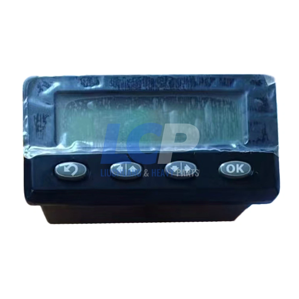
The 243-3820 module GP display, main product view. Click to enlarge.
| Attribute | Detail |
|---|---|
| Part number | 243-3820 (also written 2433820) |
| Catalog description | Module group, display (Messenger) |
| Related control group | 239-5025 monitor control group, unprogrammed |
| Revision marking | Dash suffix on the label, such as -07 or -10 |
| Typical engines | C27 and C32 industrial and petroleum configurations |
| Communication | ECM data link (SAE J1939 on most configurations) |
| Supply voltage | Engine DC system; verify on the unit label and wiring diagram |
Part numbers are listed for reference and compatibility identification only.
How Does the Display Talk to the Engine ECM?
The display reads data that the engine ECM broadcasts on the data link. It does not connect to engine sensors. Every value on screen comes from ECM messages.
On J1939 configurations, the link is a two-wire twisted pair running at 250 kbps. A 120-ohm terminating resistor sits at each end of the backbone. The display is simply one node on that network.
This design matters for diagnosis. A wiring fault anywhere on the bus can blank the display, even when the module itself is healthy.
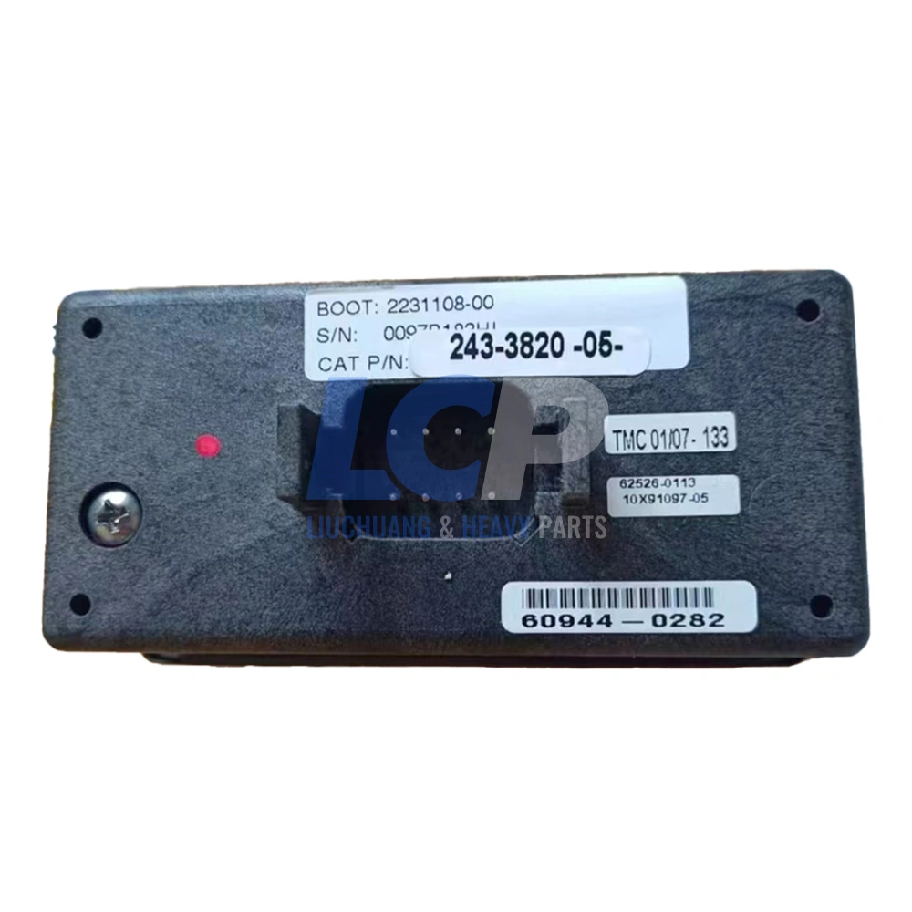
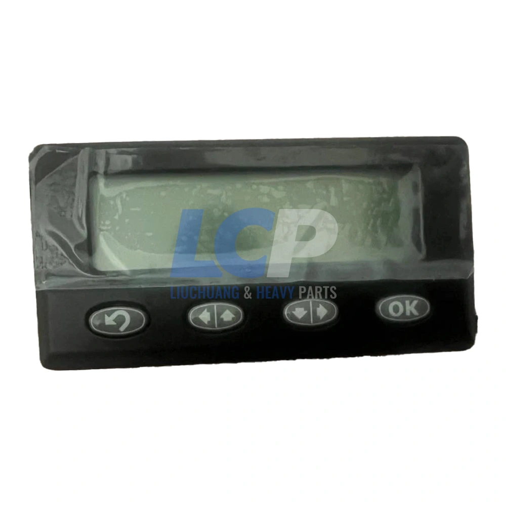
Additional views of the 243-3820 display module for fitment and part number checks. Click any image to enlarge.
What the display does
- Shows live engine parameters from the ECM
- Lists active and logged diagnostic codes
- Tracks service hours and maintenance data
- Lets operators scroll screens with soft keys
What the display does not do
- Measure oil pressure or temperature directly
- Control fuel injection or engine timing
- Replace a service tool for flash programming
- Correct a faulty sensor reading
Common Failure Symptoms
The most common symptoms are a blank screen, missing values, and random resets. Each symptom points to a different fault zone. Use the table below to narrow the search before you pull the unit.
| Symptom | What You See | Most Likely Source |
|---|---|---|
| Completely dark | No backlight at key-on | Fuse, power feed, ground, or internal power supply |
| Backlight only | Screen lit but empty | LCD driver or internal ribbon connection |
| Dashes or no data | Screens load, values missing | Data link wiring, termination, or ECM not broadcasting |
| Resets or freezes | Reboots during cranking | Voltage sag, loose ground, weak batteries |
| Dead soft keys | Cannot scroll screens | Worn membrane keypad or moisture |
| Fogged or faded | Hard to read in daylight | Seal failure or UV and heat damage |
| Values disagree with gauges | Readings differ from a mechanical gauge | Usually a sensor or ECM issue, not the display |
Why Does a 243-3820 Display Module Fail?
Most 243-3820 display module failures start in the environment around the unit, not inside it. Heavy vibration, heat, moisture, and electrical noise all shorten its service life.
Voltage Transients and Low Voltage
Starter circuits and alternators create voltage spikes on the DC system. Service literature for a related marine display documents starter-circuit transients above 100 VDC on the J1939 link. Weak batteries cause the opposite problem: brownouts that reset the display during cranking.
Vibration and Connector Fatigue
Pump and drilling packages run long hours at high load. Constant vibration loosens connector pins and cracks solder joints over time. Intermittent faults that come and go with engine speed often start here.
Moisture and Heat
Pressure washing and outdoor exposure push water past aging seals. Moisture corrodes connector terminals and fogs the LCD. Direct sun and engine heat also fade the screen and harden the keypad membrane.
Data Link Problems
A missing terminating resistor, chafed twisted pair, or failed node can disrupt the whole bus. The display then shows dashes even though it works. This is the most common cause of good units being replaced unnecessarily.
Step-by-Step Diagnostic Procedure
Diagnose the display by proving power, ground, and data link health first. Only then condemn the module. This sequence takes about 30 minutes with a digital multimeter and a service tool.
Warning: Turn the key off and disconnect the batteries before unplugging the display. Back-probe connectors instead of piercing wire insulation, which lets moisture into the harness.
- Record the symptom. Note whether the screen is dark, blank, or showing dashes. Check if the engine starts and runs normally.
- Check supply voltage. With the key on, measure voltage at the display power pins. A drop over 0.5 V versus battery voltage points to wiring or a fuse.
- Check the ground. Measure resistance from the display ground pin to battery negative. Anything above 1 ohm needs cleaning or repair.
- Test bus termination. With power off, measure CAN High to CAN Low. About 60 ohms is normal; about 120 ohms means a missing terminator.
- Connect a service tool. If the tool reads the ECM normally but the display shows no data, focus on the display branch.
- Inspect the connector. Look for green corrosion, pushed-back pins, damaged seals, and strain on the harness.
- Swap test. Install a known-good display with the same part number and revision. If the fault clears, the original unit is confirmed bad.
Pro Tip: Photograph the label on the old unit before removal. The dash revision and serial number speed up cross-reference checks and prevent ordering the wrong version.
Fault Codes You Will See on the Display
Most codes on the display describe engine or sensor faults, not display faults. The display only relays what the ECM reports. Older configurations may show CID-FMI codes instead of J1939 SPN-FMI codes.
| SPN / FMI | Meaning | Display Fault? | First Check |
|---|---|---|---|
| SPN 100 / FMI 1 | Oil pressure low, most severe | No | Verify with a mechanical gauge |
| SPN 110 / FMI 0 | Coolant temperature high, most severe | No | Cooling system and sensor check |
| SPN 168 / FMI 4 | Battery potential below normal | Can cause resets | Batteries, charging, main grounds |
| SPN 190 / FMI 2 | Engine speed signal erratic | No | Speed/timing sensor and wiring |
| SPN 639 / FMI 9 or 14 | J1939 network communication fault | Possible | Termination, twisted pair, each bus node |
Code presentation varies by engine software. Always confirm codes with a service tool before replacing parts.
Repair, Used Pull, or Tested Replacement?
For most fleets, a tested replacement is the fastest path back to service. Repair suits single, known faults. Used pulls carry the highest risk. The right choice depends on how much downtime costs your operation.
| Option | Turnaround | Main Risk | Warranty | Best Fit |
|---|---|---|---|---|
| Board-level repair | Days to weeks plus return freight | Other weak components left in place | Varies by shop | One confirmed fault, spare unit on hand |
| Used salvage pull | Fast if in stock | Unknown hours, heat, and moisture history | Often none | Short-term emergency backup |
| Tested aftermarket replacement | 24–48 hour dispatch from stock | Must match revision and software status | 12 months | Fleets that need uptime and coverage |
| Dealer-supplied new unit | Depends on dealer stock | Highest purchase cost | Dealer terms | Warranty-critical installations |
In our field experience, a pump or drilling package idled for a week costs far more than the display itself. That is why many operators keep a tested 243-3820 display module replacement on the shelf as a critical spare.
How to Choose and Install the Right Replacement
Choose a replacement by matching the full part number, dash revision, and software status of your current unit. Then install it with the batteries disconnected and verify communication before returning the engine to service.
Selection Checklist
- Part number 243-3820 matches the label on the removed unit.
- Dash revision is the same, or the supplier confirms cross-compatibility.
- Software status is known: configured and ready, or unprogrammed.
- Connector type and panel cutout match your installation.
- The supplier provides a bench test photo or video before shipment.
Installation Notes
Disconnect the batteries and remove the old unit from the panel. Transfer the mounting hardware and gasket if the new unit ships without them. Apply dielectric grease to the connector seal, not the terminals.
Reconnect power and turn the key on. Confirm that engine speed, temperatures, and pressures populate within a few seconds. Check the fault log and clear any codes left from the old unit.
Programming Notes
The 239-5025 control group is catalogued as unprogrammed. An unprogrammed unit needs flash programming with a dealer-level electronic service tool and the correct flash file. Ask your supplier to confirm the software status before ordering, and review the 243-3820 display module product details for condition and test notes.
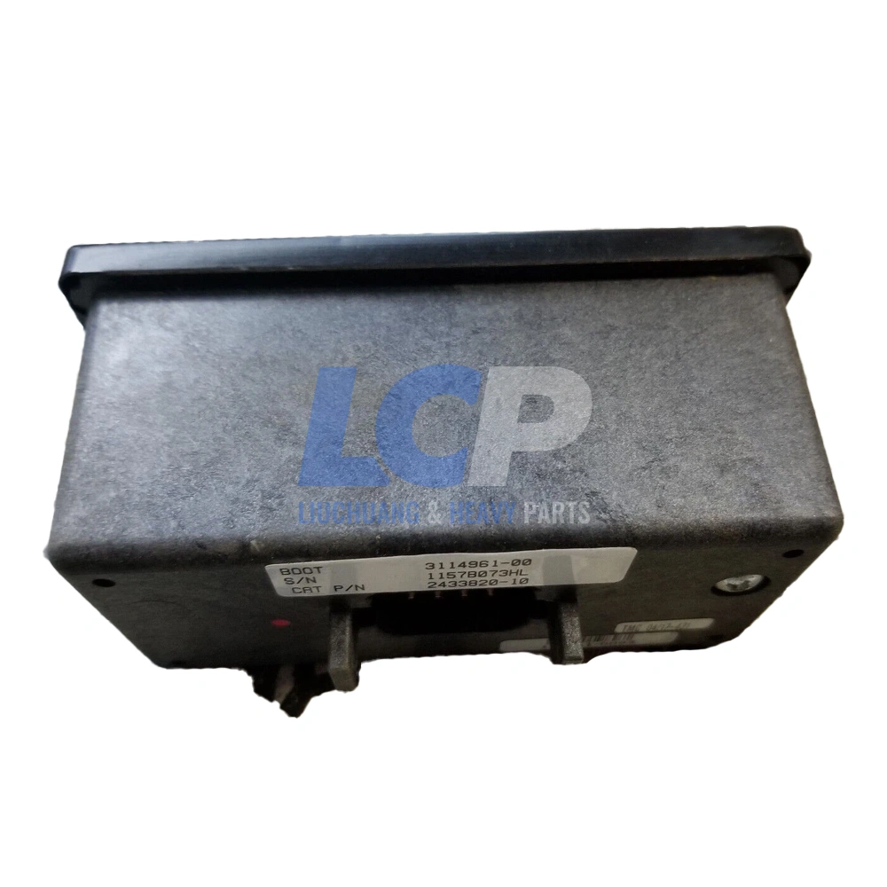
243-3820 display module inspected and ready for dispatch. Click to enlarge.
Frequently Asked Questions
What engines use the 243-3820 display module?
The 243-3820 display module is listed for C27 and C32 engines, including C32 petroleum configurations used in well service and drilling. Some listings also mention C11 packages. Always confirm fitment by matching the part number on your existing unit, not by engine model alone.
Is 243-3820 the same as 239-5025?
No, but they are related. Parts catalogs list 239-5025 as the unprogrammed monitor control group inside the 243-3820 display assembly. Ordering 239-5025 alone may require flashing software before use. The complete 243-3820 module is usually the simpler field swap.
Does a replacement display need programming?
It depends on the unit’s software status. A display with matching software usually works as soon as it is connected. An unprogrammed control group needs a flash file loaded with a dealer-level service tool. Ask your supplier to confirm status and share a power-on test photo.
Why does my display show dashes instead of readings?
Dashes usually mean the display has power but receives no data from the ECM. Measure CAN High to CAN Low with power off; about 60 ohms is normal. If a service tool reads the ECM, inspect the display branch wiring before replacing the module.
Can a failed display stop the engine from running?
In most installations, no. The engine ECM controls fueling and engine protection independently. However, operators lose sight of warnings and fault codes. Some packages route alarm or shutdown logic through the panel, so check your wiring diagram before running without a working display.
How do I confirm compatibility before ordering?
Photograph the label on your current unit and send it to your supplier. Include the full part number, dash revision, and serial number. Add the engine serial prefix and connector type. These details prevent most fitment and communication problems after installation.
Conclusion
The 243-3820 display module is the operator’s window into C27 and C32 engine data. Most complaints start with power, ground, or data link faults, so test the wiring first. When the unit itself fails, match the part number, revision, and software status before ordering. Browse our aftermarket ECM and engine display catalog for related modules.
All part numbers are cited for reference and compatibility identification only, including those compatible with Caterpillar equipment. LIUCHUANG Parts is an independent aftermarket and remanufactured parts supplier and is not affiliated with any original equipment manufacturer.
Need a Tested 243-3820 Display Module?
Every unit is tested before shipment and backed by a 12-month warranty. In-stock orders dispatch within 24–48 hours via DHL, FedEx, or UPS. Import duties and taxes, where applicable, are the buyer’s responsibility.
Check Availability & Pricing →